Notice: Any messages purporting to come from this site telling you that your password has expired, or that you need to verify your details, confirm your email, resolve issues, making threats, or asking for money, are
spam. We do not email users with any such messages. If you have lost your password you can obtain a new one by using the
password reset link.
Due to spam on this forum, all posts now need moderator approval.
Entire forum
➜ Electronics
➜ Microprocessors
➜ Timers and counters
Postings by administrators only.
Refresh page
Pages: 1
2
| Posted by
| Nick Gammon
Australia (23,173 posts) Bio
Forum Administrator |
| Date
| Reply #15 on Sat 27 Jun 2015 01:12 AM (UTC) |
| Message
| Example of generating 8 MHz signal
After a few similar queries on the forum, I post below a small sketch whose sole purpose is to output 8 MHz clock on one of the pins (the pin varies by board type). This assumes you have a 16 MHz clock. The timer toggles the pin on every clock cycle, and as one unit of "frequency" is an on/off sequence, you get half the frequency on the pin.
You could get a lower frequency by changing OCR1A below. For example, if it was 2 it would toggle at 8 MHz, which means the output frequency would be 4 MHz.
#ifdef __AVR_ATmega2560__
  const byte CLOCKOUT = 11;  // Mega 2560
#else
  const byte CLOCKOUT = 9;   // Uno, Duemilanove, etc.
#endif

void setup ()
  {
  // set up 8 MHz timer on CLOCKOUT (OC1A)
  pinMode (CLOCKOUT, OUTPUT);
  // set up Timer 1
  TCCR1A = bit (COM1A0);  // toggle OC1A on Compare Match
  TCCR1B = bit (WGM12) | bit (CS10);   // CTC, no prescaling
  OCR1A =  0;       // output every cycle
  }  // end of setup

void loop ()
  {
  // whatever
  }  // end of loop
Since this is entirely hardware-driven you can be doing other things in your main code (other than using Timer 1, of course). |
- Nick Gammon
www.gammon.com.au, www.mushclient.com | | Top |
|
| Posted by
| Nick Gammon
Australia (23,173 posts) Bio
Forum Administrator |
| Date
| Reply #16 on Sat 11 Jul 2015 09:44 PM (UTC) Amended on Sat 11 Jul 2015 09:45 PM (UTC) by Nick Gammon
|
| Message
| Example of timing an interval without interrupts
Sometimes you need to time things when interrupts are off (eg. because you are driving Neopixels, which turn off interrupts because of hardware timing requirements.)
The code below uses Timer 1 to time an interval up to 8.388 seconds. It users a prescaler of 1024, which means each "count" of timer 1 is 1/16e6 * 1024 of a second (0.000064 seconds, or 64 µS). Since it can count up to 65536 we can time 0.000064 * 65536 = 4.194304 seconds. Then the timer overflows, but we can test the "overflow flag" and know the overflow occurred. That lets us time up to 8.388608 seconds before we miss the fact that there was a second overflow.
void startTimer1 ()
  {
  // reset Timer 1
  TCCR1A = 0;
  TCCR1B = 0;
  // zero it
  TCNT1 = 0;
  TIFR1 |= bit (TOV1);  // clear overflow flag
  // start Timer 1
  TCCR1B =  bit (CS10) | bit (CS12);  //  prescaler of 1024
  }  // end of startTimer1

unsigned long getTimer1Reading ()
  {
  unsigned long elapsed = TCNT1;
  if (TIFR1 &  bit (TOV1))
     elapsed += 65536;
  return elapsed;
  }  // end of getTimer1Reading

void setup ()
  {
  Serial.begin (115200);
  Serial.println ();

  }  // end of setup

void loop ()
  {
  Serial.println ("Starting ...");
  Serial.flush ();

  startTimer1 ();

  delay (7560);
  float secs = (1.0 / F_CPU * 1024) * getTimer1Reading ();

  Serial.print ("Time taken = ");
  Serial.print (secs);
  Serial.println (" seconds.");

  }  // end of loop
Instead of the delay(7560) in the test, you could have in that place something which turns off interrupts, does something lengthy, and turns them back on again. |
- Nick Gammon
www.gammon.com.au, www.mushclient.com | | Top |
|
| Posted by
| Nick Gammon
Australia (23,173 posts) Bio
Forum Administrator |
| Date
| Reply #17 on Fri 07 Aug 2015 02:17 AM (UTC) |
| Message
| Example of doing something jitter-free every x µs
#include <avr/sleep.h>

ISR (TIMER1_COMPA_vect)
  {
  PINB = bit (5); // toggle D13
  }  // end of TIMER1_COMPA_vect

void setup ()
  {
  pinMode (13, OUTPUT);

  // stop timer 0
  TCCR0A = 0;
  TCCR0B = 0;

  // stop timer 1
  TCCR1A = 0;
  TCCR1B = 0;

  TCCR1B = bit (WGM12) |  // CTC
           bit (CS10);    // prescaler of 1

  // 1e9 / 22050 / 62.5 = 725.6 - round down, then subtract 1
  OCR1A = 724;
  TIMSK1 = bit (OCIE1A);  // interrupt on compare A

  set_sleep_mode (SLEEP_MODE_IDLE);

  }  // end of setup

void loop ()
  {
  sleep_mode ();
  }  // end of loop
The above example was for the Arduino forum, where someone wanted to send something to a DAC every 1/22050 seconds (ie. every 453.5 µs).
The code as posted doesn't actually send anything (it toggles pin 13), but in the ISR is where you would put code to do something more substantial. By sleeping in the main loop we ensure that the ISR is called without jitter, because the processor is idling. |
- Nick Gammon
www.gammon.com.au, www.mushclient.com | | Top |
|
| Posted by
| Nick Gammon
Australia (23,173 posts) Bio
Forum Administrator |
| Date
| Reply #18 on Sat 08 Aug 2015 02:47 AM (UTC) Amended on Sat 08 Aug 2015 05:04 AM (UTC) by Nick Gammon
|
| Message
| Below are some charts for working out the bit positions (and names) for the three timers on the Atmega328P (as in the Arduino Uno, Duemilanove, etc.)
The images below are thumbnails, click on them (or RH-click and "save link as") to get a full-sized image.


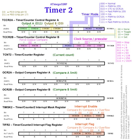

These images are licensed under a Creative Commons Attribution 3.0 Australia License. |
- Nick Gammon
www.gammon.com.au, www.mushclient.com | | Top |
|
| Posted by
| Nick Gammon
Australia (23,173 posts) Bio
Forum Administrator |
| Date
| Reply #19 on Wed 03 Feb 2016 01:05 AM (UTC) |
| Message
| Timer interrupts on the ATtiny85
Following on from a question on Arduino Stack Exchange I developed this short piece of code that calls an interrupt periodically on the ATtiny85.
// ATMEL ATTINY 25/45/85 / ARDUINO
// Pin 1 is /RESET
//
//                  +-\/-+
// Ain0 (D 5) PB5  1|    |8  Vcc
// Ain3 (D 3) PB3  2|    |7  PB2 (D 2) Ain1
// Ain2 (D 4) PB4  3|    |6  PB1 (D 1) pwm1
//            GND  4|    |5  PB0 (D 0) pwm0
//                  +----+

ISR (TIMER1_COMPA_vect)
  {
  digitalWrite (4, ! digitalRead (4));  //toggle D4 (pin 3 on chip)
  }

void setup()
 {
  pinMode (4, OUTPUT);  // chip pin 3

  // Timer 1
  TCCR1 = bit (CTC1);   // Clear Timer/Counter on Compare Match
  TCCR1 |= bit (CS10) | bit (CS13);  // prescaler of 256
  OCR1C = 123;          // what to count to (zero-relative)
  TIMSK = bit (OCIE1A); // interrupt on compare

  }  // end of setup

void loop()
  {
  // other code here
  }
You can tweak the time delay by changing both the prescaler and the counter in OCR1C. The prescaler gives you coarse tuning, which gets you into the ballpark of the delay time. The timer then counts up to give you the final delay.
In my case I chose a prescaler of 256 which is or'ing together CS10 and CS13.
The delay is then:
125 ns * 256 * 124 = 3.968 ms
Where 256 is the prescaler and 124 is what we are counting to. This is assuming an 8 MHz clock which gives a clock period of 125 ns.
See the datasheet for what bit settings to use for various prescalers. You can use a prescaler from 1 to 16384, in powers of two (ie. 1, 2, 4, 8, 16, 32 ...).
Flashing more slowly
If you put an LED on pin 3 and want to see the flashing, you need it much slower. For example:
TCCR1 |= bit (CS10) | bit (CS11) | bit (CS12) | bit (CS13); // prescaler: 16384
That toggles the pin every 254 ms, which is visible.
Warning
On this chip Timer 1 is an 8-bit timer, so you cannot put more than 255 into OCR1C. |
- Nick Gammon
www.gammon.com.au, www.mushclient.com | | Top |
|
| Posted by
| Nick Gammon
Australia (23,173 posts) Bio
Forum Administrator |
| Date
| Reply #20 on Sun 03 Mar 2024 08:42 PM (UTC) |
| Message
| Example of generating a 10 kHz signal with its inverse
As suggested by Edgar Bonet on Arduino Stack Exchange you can output a signal on pin 3 and its inverse on pin 11 using Timer 2.
void setup() {
    TCCR2B = 0;           // stop Timer 2
    TCNT2  = 0;           // reset timer
    TCCR2A = bit(COM2A0)  // toggle OC2A on compare match
           | bit(COM2B0)  // toggle OC2B on compare match
           | bit(WGM21);  // mode 2 = CTC, TOP = OCRA
    OCR2A  = 99;          // timer period = 100 * 2 * 8 / C_CPU
    OCR2B  = 99;          // toggle OC2A and OC2B simultaneously
    TCCR2B = bit(CS21)    // clock @ F_CPU/8
           | bit(FOC2B);  // force output compare B: invert OC2B signal
    DDRB  |= bit(PB3);    // OC2A = PB3 = digital 11 as output
    DDRD  |= bit(PD3);    // OC2B = PD3 = digital 3 as output
}

void loop(){}
Since this uses CTC mode you cannot do PWM (ie. you cannot vary the duty cycle) however it shows how a signal and its inverse can be produced. |
- Nick Gammon
www.gammon.com.au, www.mushclient.com | | Top |
|
The dates and times for posts above are shown in Universal Co-ordinated Time (UTC).
To show them in your local time you can join the forum, and then set the 'time correction' field in your profile to the number of hours difference between your location and UTC time.
414,401 views.
This is page 2, subject is 2 pages long: ![[Previous page]](/images/thin_prev.gif) 1
2
1
2
Postings by administrators only.
Refresh page
![[Go to top]](/images/gototop.gif) top
top


